How Drill Bits Are Made: A Practical Manufacturing Guide
Explore the end-to-end process of drill manufacturing, from alloy selection to coatings and quality control, with practical guidance for wood, metal, and masonry drilling.

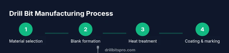
How are drills made? In short, drill manufacturing blends raw materials, precise geometry, heat treatment, coating, and rigorous quality checks to produce reliable cutting tools. The process varies by drill type (twist, spade, masonry), but all share predictable stages from alloy selection to final sharpening and inspection. Understanding these steps helps DIYers pick the right bit and anticipate performance across wood, metal, or concrete applications.
How drills are designed: materials, geometry, and coatings
To answer how are drills made, we start with materials: high-speed steel (HSS), carbide, cobalt alloys, and ceramic coatings. The choice affects hardness, heat resistance, and wear. Drill geometry, including point angle, flute count, and helix, determines cutting efficiency and heat management. Coatings like titanium nitride reduce wear and extend life. Designers also consider shank compatibility for drill presses or hand-held drivers, plus standardized tolerances that ensure bits fit common chucks. This planning stage directly influences performance across wood, metal, and masonry applications and sets the stage for the manufacturing workflow ahead.
The core manufacturing stages: blanks to cutting edges
manufacturing begins with selecting a suitable alloy and creating a cylindrical blank with a shank segment. The blank is formed with precise diameters and concentricity to ensure balance during rotation. Milling and turning machines sculpt the blank to near-final dimensions, creating the basic geometry that will become the flute and land after grinding. During this phase, quality-control checks verify roundness and surface finish, because even tiny deviations can affect cutting efficiency after heat treatment.
Heat treatment and tempering explained
Heat treatment hardens the metal to achieve cutting strength, wear resistance, and thermal stability. Blanks are heated to controlled temperatures, then quenched in oil or air to harden the core. Tempering follows to reduce brittleness, improving toughness under impact. The exact temperatures and soaking times depend on the material family (HSS, carbide, cobalt) and the intended use (wood, metal, or masonry). Consistency in this step is crucial; improper heat treatment can cause premature wear or breakage.
Grinding and shaping the flutes (the cutting action)
Grinding machines shape the primary flute geometry, helix angle, and land—the flat surface left after grinding. Advanced CNC grinders ensure every flute is uniform, which minimizes vibration and maximizes drilling efficiency. The process also forms relief behind the cutting edge to prevent rubbing and heat buildup during cutting. Proper wheel conditioning and dressing are essential to maintain sharpness and consistent edge geometry across long production runs.
Tip formation and edge honing
The tip is ground to a precise point geometry—commonly a 118-degree or 135-degree point for general-purpose bits—along with relief cuts that optimize penetration. A micro-edge is honed to create a clean, durable cutting edge capable of slicing through the target material with minimal stress. This step often incorporates multi-axis grinders and optical inspection to ensure accuracy, as even small deviations affect hole quality and speed.
Coatings and marking for performance and traceability
Coatings such as titanium nitride (TiN) or aluminum oxide increase hardness, reduce friction, and extend tool life. After coating, bits are laser-marked for traceability, including batch IDs, material family, and size. Coatings must be uniform to avoid weak spots that could peel or flake during use. Traceability supports quality control and helps customers select the right bit for their job.
Quality control: measuring accuracy and wear
Throughout production, inspectors measure diameter tolerance, runout, and surface finish. Random samples undergo metallographic examination and hardness testing to verify process consistency. Coating thickness and adhesion are checked with dedicated instruments. Any part failing critical criteria is rejected to prevent subpar bits from entering the market.
Production variants: wood, metal, masonry drills
Different families of drills—wood, metal, and masonry—share core manufacturing steps but diverge in geometry, coatings, and tolerances. Wood bits emphasize sharpness and clean cuts without excessive rubbing; metal bits prioritize heat resistance and toughness; masonry bits feature reinforced tips and carbide compositions to resist brittle failure when breaking through stone or concrete. Tailoring the processes ensures each family meets its material-specific demands.
Sustainability, safety, and future trends in drill manufacturing
Manufacturers increasingly adopt energy-efficient furnaces, waste-minimization practices, and recycling of worn carbide and steel scrap. Safety protocols cover high-temperature operations, grinding dust, and handling sharp edges. Trends point toward higher-performance carbide-tipped designs and smarter coatings that balance durability with cost, helping pros work faster while reducing waste.
Packaging, distribution, and end-of-life considerations
Finished drill bits are packaged in protective inserts to prevent chipping, with clear size labeling and material specifications. Packaging materials are chosen to minimize environmental impact, and many brands offer recycling programs for worn bits. End-of-life considerations include redesigns for more efficient disposal and enhanced reuse of worn tools in secondary markets.
toolsMaterialsBlockComment: null
Tools & Materials
- Alloy blanks (HSS, carbide, or cobalt alloys)(Choose according to intended application and coating compatibility.)
- Grinding wheels and CNC grinders(Maintain wheel wear and periodic dressing for precision edges.)
- Heat-treatment furnaces(Controlled temperatures and quenching media (oil/air) per material.)
- Coating equipment (PVD/CVD)(Optional for specialty coatings like TiN or TiAlN.)
- Laser marking system(For batch traceability and size identification.)
- Inspection gauges and optical comparators(Quality control for diameter, runout, and edge quality.)
- Lubricants and coolant(Keep tools cool during grinding to prevent loss of hardness.)
Steps
Estimated time: 8-12 hours total
- 1
Define specifications
Document the target material, hole size, tolerance range, desired coating, and shank type. This decision sets all subsequent steps and influences hardness, flute geometry, and coating choices.
Tip: Record tolerances clearly to avoid drift in later grinding and polishing stages. - 2
Prepare raw material blanks
Source appropriate alloy blanks and inspect for surface defects. Cut or forge to near-net shape to minimize waste in later steps.
Tip: Check for microscopic surface imperfections that could propagate cracks during heat treatment. - 3
Rough-form the blank into a drill blank
Use turning/milling to achieve the basic diameter and shank size, ensuring concentricity and balance for smooth operation.
Tip: Maintain coolant flow to reduce heat and micro-wrinkles on the blank surface. - 4
Hardening and tempering
Heat the blank to a controlled temperature, quench to harden, then temper to achieve the balance between hardness and toughness.
Tip: Monitor temperature precisely; uneven heating can cause uneven hardness across the bit. - 5
Grind primary flute geometry and lands
Shape the main flute and lands with CNC grinders to create efficient cutting geometry and proper chip removal.
Tip: Regularly verify flute symmetry to prevent vibration during drilling. - 6
Ground tips and edge honing
Form the point geometry and hone the cutting edge to ensure a clean, sharp start in material contact.
Tip: Use optical inspection to confirm point angle accuracy before coating. - 7
Apply coating and mark
Deposit the chosen coating and laser-mark size and batch identifiers for traceability.
Tip: Ensure coating thickness uniformity to avoid flaking under load. - 8
Quality inspection and packaging
Test tolerance, runout, coating adhesion, and edge sharpness on samples before packaging and batch release.
Tip: Reject parts that fail any critical spec to protect end-user performance.
Got Questions?
What materials are commonly used to make drill bits?
Common drill bit materials include high-speed steel (HSS), cobalt alloys, and carbide for different performance needs. Some types also use coatings to improve wear resistance.
Common materials are HSS, cobalt, and carbide, chosen for the job and coated for wear resistance.
Why do drill bits have coatings like TiN?
Coatings reduce friction, increase hardness, and extend tool life, especially under high-speed drilling or hard materials.
Coatings cut wear and heat, helping bits last longer.
Are wood, metal, and masonry drill bits manufactured the same way?
They share core processes but differ in geometry, coatings, and tolerances tailored to each material. Wood bits favor clean cuts, metal bits stress hardness, and masonry bits use carbide edges for stone or concrete.
All drill types start the same, but geometry and coatings differ by material.
How can I choose the right drill bit for a project?
Consider material to be drilled, drilling speed, hole size, and required finish. Match the bit type, point angle, and coating to the task.
Think about what you’re drilling, the material, and the finish you want.
What is the typical lead time for manufacturing a batch of drill bits?
Lead times vary by batch size and complexity; manufacturers plan around production schedules and coating runs.
Lead times depend on batch size and process steps, like coating.
Is drill bit manufacturing dangerous?
Yes, due to high temperatures, sharp edges, and rotating equipment. Proper PPE and safe handling are essential.
It can be dangerous if safety rules aren’t followed.
Watch Video
Top Takeaways
- Define clear specs before production
- Maintain strict quality checks at every stage
- Different drill families require different geometry/coatings
- Coatings extend tool life but must be uniform
- Safety and sustainability matter in modern manufacturing